Transmission impairments
Signals travel through transmission media, which are not perfect. The imperfection causes signal impairment. This means that the signal at the beginning of the medium is not the same as the signal at the end of the medium. What is sent is not what is received. Three causes of impairment are attenuation, distortion, and noise.
 |
| impairments |
1.Attenuation
Means loss of energy -> weaker signal When a signal travels through a medium it loses energy overcoming the resistance of the medium
Amplifiers are used to compensate for this loss of energy by amplifying the signal.
Measurement of Attenuation
To show the loss or gain of energy the unit “decibel” is used.
dB = 10log10P2/P1
P1 - input signal
P2 - output signal
The attenuation leads to several problems:
People also ask by GOOGLE
Attenuation Distortion:
If the strength of the signal is very low, the signal cannot be detected and interpreted properly at the receiving end. The signal strength should be sufficiently high so that the signal can be correctly detected by a receiver in presence of noise in the channel. As shown in Fig. ,an amplifier can be used to compensate the attenuation of the transmission line. So, attenuation decides how far a signal can be sent without amplification through a particular medium.
Attenuation of all frequency components is not same. Some frequencies are passed without attenuation, some are weakened and some are blocked. This dependence of attenuation of a channel on the frequency of a signal leads to a new kind of distortion attenuation distortion. As shown in Fig(Attenuation distortion of a square wave after passing through a medium). a square wave is sent through a medium and the output is no longer a square wave because of more attenuation of the high-frequency components in the medium.
 |
| Attenuation distortion of a square wave after passing through a medium |
The effect of attenuation distortion can be reduced with the help of a suitable equalizer circuit, which is placed between the channel and the receiver. The equalizer has opposite attenuation/amplification characteristics of the medium and compensates higher
losses of some frequency components in the medium by higher amplification in the equalizer. Attenuation characteristics of three popular transmission media are shown in Fig.. As shown in the figure, the attenuation of a signal increases exponentially as frequency is increased from KHz range to MHz range. In case of coaxial cable attenuation increases linearly with frequency in the Mhz range. The optical fibre, on the other hand, has attenuation characteristic similar to a band-pass filter and a small frequency band in the THz range can be used for the transmission of signal
 |
| Attenuation characteristics of the popular guided media |
Example:
Suppose a signal travels through a transmission medium and its power is reduced to one-half. This means that P2 is (1/2)P1. In this case, the attenuation (loss of power) can be calculated as
 |
| Attenuation examle |
A loss of 3 dB (–3 dB) is equivalent to losing one-half the power.
2.Distortion
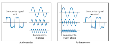
Means that the signal changes its form or shape
Distortion occurs in composite signals
Each frequency component has its own propagation speed traveling through a medium.
The different components therefore arrive with different delays at the receiver.
That means that the signals have different phases at the receiver than they did at the source.
 |
Distortion
People also ask by GOOGLEframing in computer network || what is framing?2.1 Delay distortion
The velocity of propagation of different frequency components of a signal are different in guided media. This leads to delay distortion in the signal. For a bandlimited signal, the velocity of propagation has been found to be maximum near the center frequency and lower on both sides of the edges of the frequency band. In case of analog signals, the received signal is distorted because of variable delay of different components. In case of digital signals, the problem is much more severe. Some frequency components of one bit position spill over to other bit positions, because of delay distortion. This leads to intersymbol interference, which restricts the maximum bit rate of transmission through a particular transmission medium. The delay distortion can also be neutralised, like attenuation distortion, by using suitable equalizers.
3.Noise
mixed up with the signal, along with the distortion introduced by the transmission media. Noise can be categorised into the following four types:
a. thermal noise: The thermal noise is due to thermal agitation of electrons in a conductor. It is distributed across the entire spectrum and that is why it is also known as white noise (as the frequency encompass over a broad range of frequencies).
b.intermodulation noise: When more than one signal share a single transmission medium, intermodulation noise is generated. For example, two signals f1 and f2 will generate signals of frequencies (f1 + f2) and (f1 - f2), which may interfere with the signals of the same frequencies sent by the transmitter. Intermodulation noise is introduced due to nonlinearity present in any part of the communication system.
c.Cross talk : Cross talk is a result of bunching several conductors together in a single cable. Signal carrying wires generate electromagnetic radiation, which is induced on other conductors because of close proximity of the conductors. While using telephone, it is a common experience to hear conversation of other people in the background. This is known as cross talk.
d.Impulse noise: Impulse noise is irregular pulses or noise spikes of short duration generated by phenomena like lightning, spark due to loose contact in electric circuits, etc. Impulse noise is a primary source of bit-errors in digital data communication. This kind of noise introduces burst errors.
Signal to Noise Ratio (SNR) To measure the quality of a system the SNR is often used. It indicates the
strength of the signal wrt the noise
power in the system.
It is the ratio between two powers.
It is usually given in dB and referred to as SNRdB.
Example
The power of a signal is 10 mW and the power of the
noise is 1 μW; what are the values of SNR and SNRdB ?
Solution
The values of SNR and SNRdB can be calculated as
follows:
The values of SNR and SNRdB for a noiseless channel are
We can never achieve this ratio in real life; it is an ideal
two cause of Two cases of SNR: a high SNR and a low SNR
|


Post a Comment
have you a any doubt then tell and if you want some topic then please tell .